




A sheet metal bracket, enclosure, or machine cover may appear simple on a drawing. It may contain only a few holes, several bends, and one or two welded joints. In production, however, these features interact with one another. A small variation created during one operation can affect the dimensions produced by every operation that follows.
This is what makes precision sheet metal fabrication different from ordinary sheet metal work. Accuracy cannot be judged only by the cutting result or by the specification of a single machine. The complete process—from drawing review and blank preparation to bending, welding, inspection, and assembly—must be planned as one connected manufacturing system.
Why Precision Sheet Metal Parts Are Difficult to Control
Most precision sheet metal components pass through several manufacturing stages. A flat blank may be laser cut or punched, deburred, bent multiple times, welded to another component, and then finished or assembled. Each stage introduces a certain amount of variation.
The difficulty is not necessarily that one operation produces a large error. More often, several small variations accumulate. A cut edge may be slightly different from its nominal position. A bend may open by a fraction of a degree after the pressure is released. Welding may pull two surfaces toward the joint. By the time the part reaches assembly, these changes can affect hole alignment, overall dimensions, panel flatness, or the gap between mating components.
Custom production adds another layer of complexity. Manufacturers frequently need to process different materials, thicknesses, geometries, and quantities on the same equipment. A parameter that works well for one part may not produce the same result on another.
For this reason, simply applying very tight tolerances to every dimension is rarely the best solution. It increases manufacturing and inspection costs without necessarily improving the function of the part. A better approach is to identify the dimensions that control fit, alignment, sealing, movement, or structural performance and then build the process around those features.
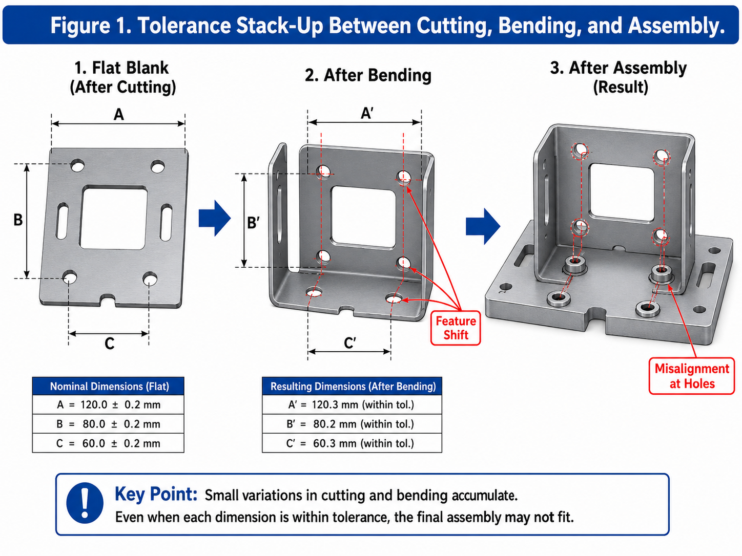
1. Tolerance Stack-Up Between Cutting, Bending, and Assembly
One of the most common problems in precision fabrication is a part that passes individual dimensional checks but does not assemble correctly.
Consider a mounting bracket with two flanges and several installation holes. The flat blank may be cut accurately, and every hole may be in the correct position before forming. After the flanges are bent, however, the relationship between the holes can change. Bend location, bend angle, material movement, and the selected measurement datum all influence the final hole-to-hole distance.
The problem becomes more noticeable when dimensions are chained from one edge to the next. Each dimension may remain within its own tolerance, but the total variation at the last feature can be much larger than expected.
A practical solution begins with the drawing. Dimensions that affect assembly should be referenced from stable, functional datums rather than from a long chain of intermediate features. The manufacturer also needs to understand which dimensions are inspected in the flat state and which must be verified after bending or welding.
Tolerance decisions should follow the function of the part. Mounting holes, locating surfaces, connector openings, and mating edges may require close control. A non-critical external edge may allow more variation. Separating these requirements helps the fabricator focus process control where it has a measurable effect on assembly.
2. Bend Springback and Feature Movement
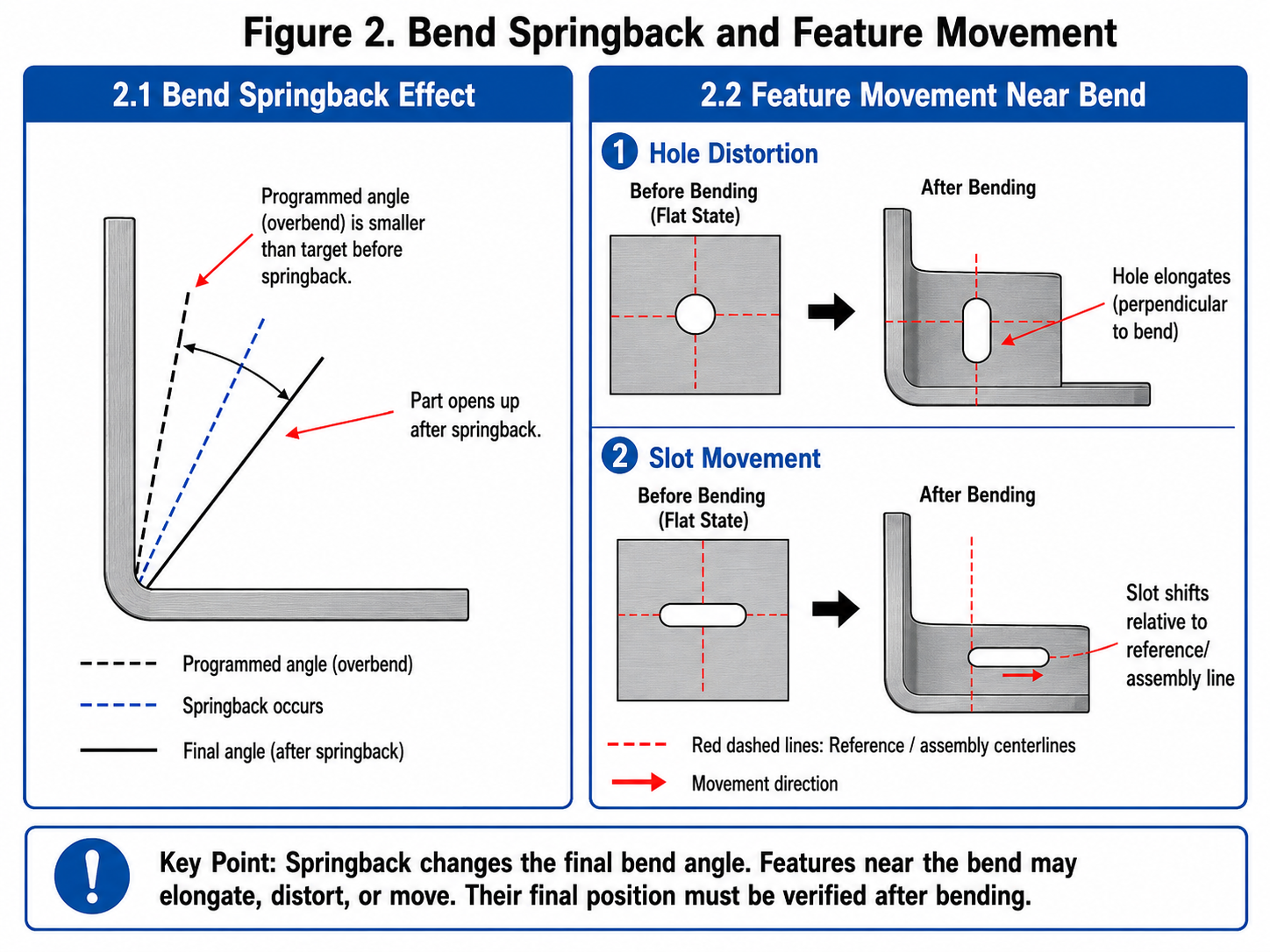
Bending is not a purely geometric operation. When a sheet is forced into a die, part of the material deforms permanently while another part attempts to return toward its original shape. This elastic recovery is known as springback.
Springback is affected by material grade, thickness, mechanical properties, grain direction, bend radius, tooling, and forming method. Two sheets with the same nominal material and thickness can still respond differently if their actual properties come from different production batches.
This is why a programmed bend angle does not automatically guarantee the required final angle. The process may need overbending or another form of compensation. Bend allowance and bend deduction must also reflect the actual combination of material, thickness, inside radius, and tooling rather than a generic value used for every project.
Features close to a bend require particular attention. Holes, slots, notches, and narrow edges can stretch or distort as material flows around the bend. A hole that is round in the flat pattern may become slightly elongated after forming. A slot may move relative to an assembly surface even though its original cutting position was correct.
These issues are best addressed before volume production. Trial bends or first-article parts can be used to verify the actual angle, flange length, and feature position. The measured result can then be used to adjust the flat pattern and forming parameters. Once the process is stable, those settings should be recorded so that later batches do not depend entirely on manual adjustment.
3. Welding Distortion in Thin Sheet Metal Assemblies
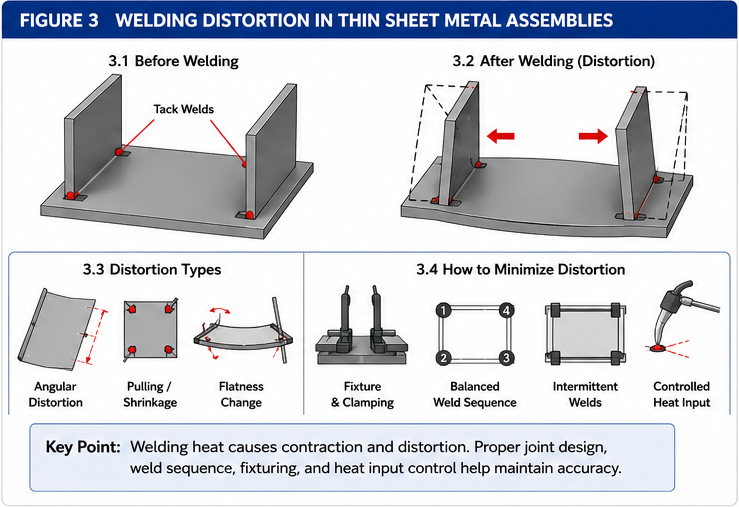
Welding introduces concentrated heat into the part. As the heated area cools, it contracts. In thin sheet metal, this contraction can change panel flatness, frame squareness, hole locations, and the distance between assembly surfaces.
For example, the individual panels of an equipment enclosure may meet their dimensional requirements before welding. After the panels are joined, the enclosure may develop a diagonal difference, a twisted corner, or an uneven door gap. The weld itself may be strong and visually acceptable, while the finished assembly no longer fits the surrounding components.
Trying to correct this problem only through grinding or cosmetic finishing is usually ineffective. Grinding may improve the appearance of a weld, but it cannot reliably restore a displaced mounting hole or a distorted frame.
Weld sequence and fixturing are therefore part of dimensional control. The fabricator needs to determine where the assembly will be located, which surfaces must remain fixed, and how heat will be distributed. Tack welding, balanced weld sequences, intermittent welds, suitable joint design, and controlled heat input can all help reduce movement.
Inspection should also take place immediately after welding, before powder coating, plating, or final assembly. At this stage, dimensions can still be evaluated and the welding method can be adjusted if necessary. Discovering distortion only after finishing usually makes correction slower and more expensive.
How Hofengfab Approaches These Precision Fabrication Challenges
The value of a manufacturing partner is not measured only by the number of machines in the workshop. It is also measured by how effectively the supplier connects design review, process planning, production, and inspection.
Hofengfab approaches precision sheet metal fabrication by first reviewing the drawing and the intended function of the component. This review may include the dimensional datums, assembly interfaces, critical hole locations, bend details, weld requirements, and areas where the specified tolerance may be difficult to maintain after forming.
The goal is not to redesign the customer’s product unnecessarily. It is to identify manufacturing risks before material is cut. When a potential conflict is found, the engineering team can discuss changes such as adjusting a bend radius, moving a feature away from a bend, changing the dimensioning method, or clarifying which surfaces control the final assembly.
Connecting the Operations Instead of Treating Them Separately
Hofengfab’s sheet metal capabilities include laser cutting, CNC punching, bending, welding, deburring, finishing, and assembly. For a precision project, these processes are planned according to the final condition of the part rather than evaluated as isolated operations.
A hole used for assembly, for example, should not be considered complete simply because it was cut accurately. Its location may need to be checked again after nearby bends are formed. In the same way, an enclosure frame may need dimensional verification after welding, not only before the panels are joined.
For parts affected by springback, a prototype or first article can be used to confirm the bend result. The actual measurements provide a basis for modifying bend compensation, tooling selection, or the developed flat pattern. For welded structures, fixtures and welding sequences can be arranged around the surfaces and dimensions that must remain stable.
This process-based approach is more reliable than repeatedly correcting finished parts. It also creates useful manufacturing data that can be applied when the same component is produced again.
Inspecting Critical Features at the Right Stage
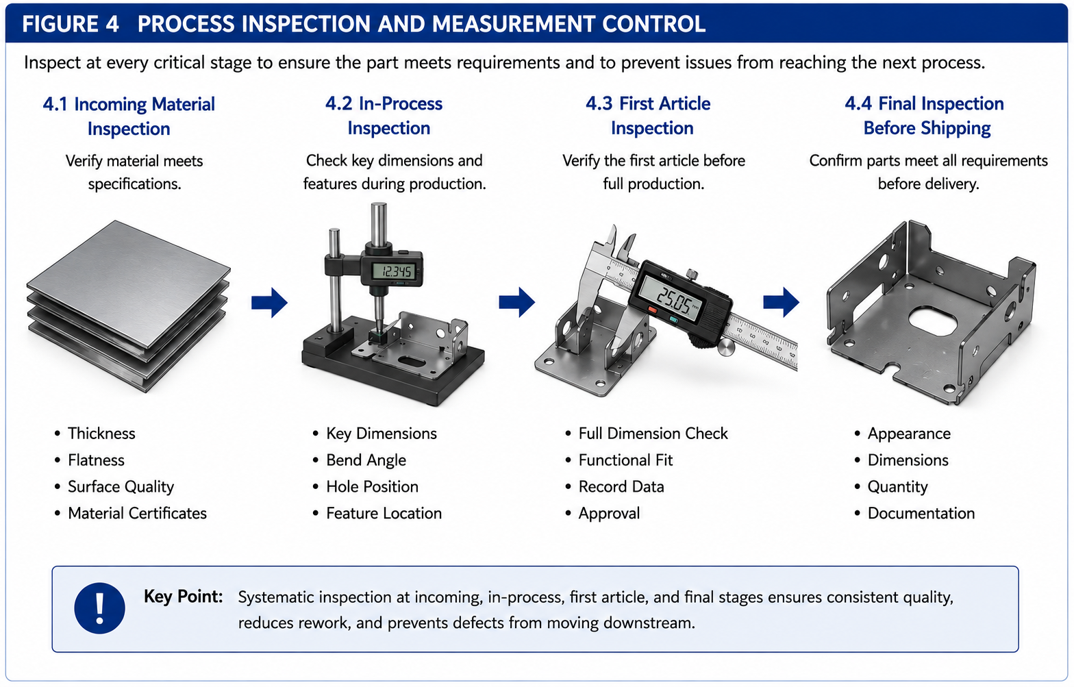
Final inspection alone cannot prevent every sheet metal problem. If a critical dimension changes during bending, it is more efficient to detect the change after bending than after welding and surface finishing have already been completed.
Hofengfab uses incoming, in-process, and final inspection as different control points. Incoming checks help confirm that the material matches the production requirements. In-process inspections can verify first-article dimensions, bend angles, hole relationships, and welded assembly conditions. Final inspection confirms that the finished components meet the agreed drawing and quality requirements before shipment.
Depending on the geometry and inspection requirements, calibrated measuring tools, optical inspection equipment, or coordinate measuring machines may be used. The inspection method should match the feature being measured. A simple flange length may require a conventional gauge, while a complex relationship between several surfaces may require a more structured measurement method.
The purpose of inspection is not only to accept or reject a finished part. Measurement results should also be used to improve cutting programs, bend compensation, fixture design, and welding procedures.
Precision Is a Process Result
Precision sheet metal fabrication is sometimes described mainly in terms of machine accuracy. In practice, the final result depends on much more than the cutting tolerance of a laser or the positioning accuracy of a press brake.
Reliable parts come from controlling how dimensions change as the material moves through each manufacturing stage. Functional datums must be clear. Bend behavior must be verified. Welding distortion must be anticipated. Critical dimensions must be inspected before later operations make correction difficult.
When these elements are considered together, it becomes easier to produce sheet metal components that not only match the drawing but also fit and function correctly in the final assembly.
For an effective project review, customers can provide Hofengfab with the CAD model, technical drawing, material and finish requirements, expected production quantity, and information about the most important assembly dimensions. With this information, the manufacturing team can evaluate the process and propose a practical production approach before fabrication begins.
お問い合わせ: mia@hofengfab.com