




3D printing is frequently used in enclosure projects before tooling begins.
For some customers, the prototype is mainly used to check the overall size and appearance. For others, it needs to hold the actual PCB, connectors, screws, flexible components or cable glands so the complete assembly can be tested.
This is where physical prototypes become useful.
We have worked on projects where a large thin wall deformed after printing, where TPU and PA-CF parts had to be assembled together before the remaining quantity was produced, and where certain MJF joint surfaces were deliberately left without bead blasting because the customer wanted to evaluate the original fit.
These details are difficult to judge from a CAD model alone.
A 1.2 mm Wall Looked Different Once the Part Was Printed
One of our prototype projects included a relatively large flat surface with a wall thickness of about 1.2 mm.
Deformation became a concern after the part was produced.
This was not simply a question of whether the printer could physically create a 1.2 mm wall. The enclosure still had to retain enough shape and stability for the customer to evaluate the part.
If a large panel is distorted, other checks can also become more difficult:
- cover and body alignment
- أسطح التلامس
- internal clearance
- mounting points
- screw positions
- overall enclosure geometry
The design was later moved toward approximately 3 mm wall thickness, and MJF PA12 was also considered as the manufacturing approach changed. At another stage, a thicker wall in the range of approximately 4–5 mm was discussed depending on the geometry and what the prototype needed to achieve.
We would not turn those numbers into a general wall-thickness rule.
A small 1.2 mm feature and a large 1.2 mm enclosure panel are very different parts.
The size of the flat area, material, printing process, build orientation and intended use of the prototype all affect the result.
Practical point
Minimum printable wall thickness is useful when checking manufacturability, but it does not tell the whole story for a functional enclosure.
The prototype may need enough stiffness to be picked up repeatedly, screwed together, fitted with a PCB and shipped to the customer for evaluation.
That places different demands on the part.
Sometimes We Print Only a Few Parts First
Another project involved components made from TPU and PA-CF.
The customer needed to check more than individual part geometry. Two components had to work together, including sliding assembly, and the effect after bonding also needed to be reviewed.
A limited number of parts were produced first for testing.
This gave the customer an opportunity to see how the actual interfaces behaved before moving ahead with the rest of the quantity.
Photos and videos can also be useful at this stage because the customer may not be physically present at the factory.
If the assembly is too tight, too loose or difficult to operate, there is still time to modify the model and repeat the test.
This approach is particularly useful for prototypes containing:
- sliding features
- snap-fits
- flexible TPU components
- mating housings
- bonded parts
- press-fit features
- covers with controlled clearance
Once the fit is confirmed, the remaining parts can be produced with much more confidence.
For early development work, one good test assembly can provide more useful information than a larger batch of identical parts produced before the interface has been checked.
Build Orientation Can Be Part of the Test
In one project, the customer requested that two parts be produced in the same build, with the same orientation and at a 45° inclination.
The parts were being evaluated together, so keeping the printing conditions consistent was important to the test.
Build orientation is sometimes treated as something only the printing supplier needs to consider.
For mating prototype parts, it can become part of dimensional control.
If two components are printed under very different conditions and then compared for fit, it becomes harder to understand whether a result came from the design itself or from process variation.
The required level of control depends on what the customer is trying to verify.
A simple visual model does not need the same approach as two components being used to study a sliding interface.
The Project May Change From FDM to MJF
The manufacturing process can also change while the prototype is being developed.
We have seen a project move between FDM PA-CF and MJF PA12 as the customer reconsidered the design and the required dimensional behavior.
That affects more than the printing quotation.
A design prepared around FDM behavior may need another review when it moves to MJF. Wall thickness, tolerances, orientation, support requirements, surface condition and mating features can all become part of the discussion again.
The CAD file should therefore not always be treated as frozen simply because a first prototype has already been printed.
Prototype development is often iterative:
Print → assemble → check → modify → print again
That is one of the main reasons to do this work before committing to a production mold.
Post-Processing Can Affect the Fit
One of the more useful lessons from our MJF work involved bead blasting.
In a prototype project, the customer specifically requested that the joint areas should not be bead blasted.
Those surfaces were being used to evaluate the fit between parts.
Applying the same finishing process over the entire component could have changed the surface condition at the interface and added another variable to the test.
So the part did not need identical treatment everywhere.
For an enclosure prototype, we normally look at each area according to what it needs to do.
| Area | Main concern | Possible treatment |
|---|---|---|
| Exterior surface | Appearance | Sanding, bead blasting, polishing |
| Mating surface | Fit and clearance | Minimal treatment or controlled finishing |
| Screw hole | Fastener installation | Drilling, tapping, cleanup |
| PCB mounting point | Position and fit | Local machining, cleanup, inserts |
| Connector opening | Hardware installation | Drilling, reaming, machining |
| Internal surface | Clearance | Support removal, local cleanup |
This is particularly important when the prototype is being used for dimensional validation.
A smoother surface may look better in a photograph, but the customer may care much more about whether the cover closes correctly or whether two mating parts slide together.
Connector and Cable-Entry Openings Need Real Hardware Checks
Enclosures rarely exist by themselves.
They normally need to accommodate connectors, switches, موصلات الكابلات, displays, PCB assemblies and mounting hardware.
We pay particular attention to these areas during prototype checking.
Common examples include:
- USB openings
- RJ45 openings
- circular connectors
- M12 connectors
- M16 / M20 / M25 cable glands
- push buttons
- المفاتيح
- ventilation components
A hole that matches the nominal CAD diameter may still need finishing before the real component installs correctly.
The connector body may need additional clearance.
A cable gland may fit through the opening but not seat correctly.
A nut may not have enough room to rotate inside the enclosure.
The connector may also interfere with a PCB, boss or internal wall that looked acceptable when each feature was reviewed separately.
Physical assembly catches these details quickly.
For customers who can provide the actual connector specification or mating hardware, prototype verification becomes much more useful.

Threads and Inserts Need Attention Too
Some prototype enclosures include printed threads.
Others use brass threaded inserts, heat-set inserts or other fastening methods.
If the cover will only be installed once for a basic size check, a simple printed feature may be enough.
A prototype that will be opened and closed repeatedly during testing has different requirements.
We often look at the whole fastening area:
- screw boss diameter
- wall thickness around the boss
- insert position
- screw alignment
- cover clearance
- distance from the PCB
- repeated assembly requirements
A screw hole can be correctly located and still create a problem if the surrounding boss interferes with another component.
This is another reason enclosure prototypes benefit from complete assembly rather than inspection of the empty housing alone.

Nylon Is Common for Functional Prototypes
Nylon is commonly considered for enclosure prototypes that need to be handled, assembled and tested.
The exact material and printing process still depend on the project.
MJF PA12 may be suitable for one housing, while another development project may use FDM materials because speed, cost, size or material behavior is more important at that stage.
Material selection becomes easier when the intended test is clear.
A prototype used for appearance review has different requirements from one that will be screwed together repeatedly and fitted with real electronic hardware.
This is also why we prefer to know what the customer plans to do with the sample.
Simply writing “3D printed prototype” on an RFQ does not always provide enough information to choose the most useful process.
What We Usually Check Before Tooling
Before the enclosure design moves toward tooling, these are some of the items worth confirming on the physical prototype:
Overall size
Does the enclosure fit within the available equipment space?
PCB installation
Can the PCB be inserted and secured without interference?
PCB mounting height
Are the bosses and stand-offs positioned correctly?
Cover fit
Does the cover sit evenly after the internal components are installed?
Mating clearance
Do sliding, locating or overlapping features assemble correctly?
Connector locations
Can real connectors be installed without interference?
Cable entries
Are hole size, position and internal access suitable for the gland or cable?
Fastening method
Are screws, inserts and bosses practical for repeated assembly?
Wall thickness
Are large panels stable enough for the intended use?
Post-processing areas
Are there surfaces that should remain untouched for dimensional evaluation?
Production process
Will the final part be injection moulded, machined, fabricated from sheet metal, or continue to use additive manufacturing?
Some of these issues may require another prototype round. That is normal.
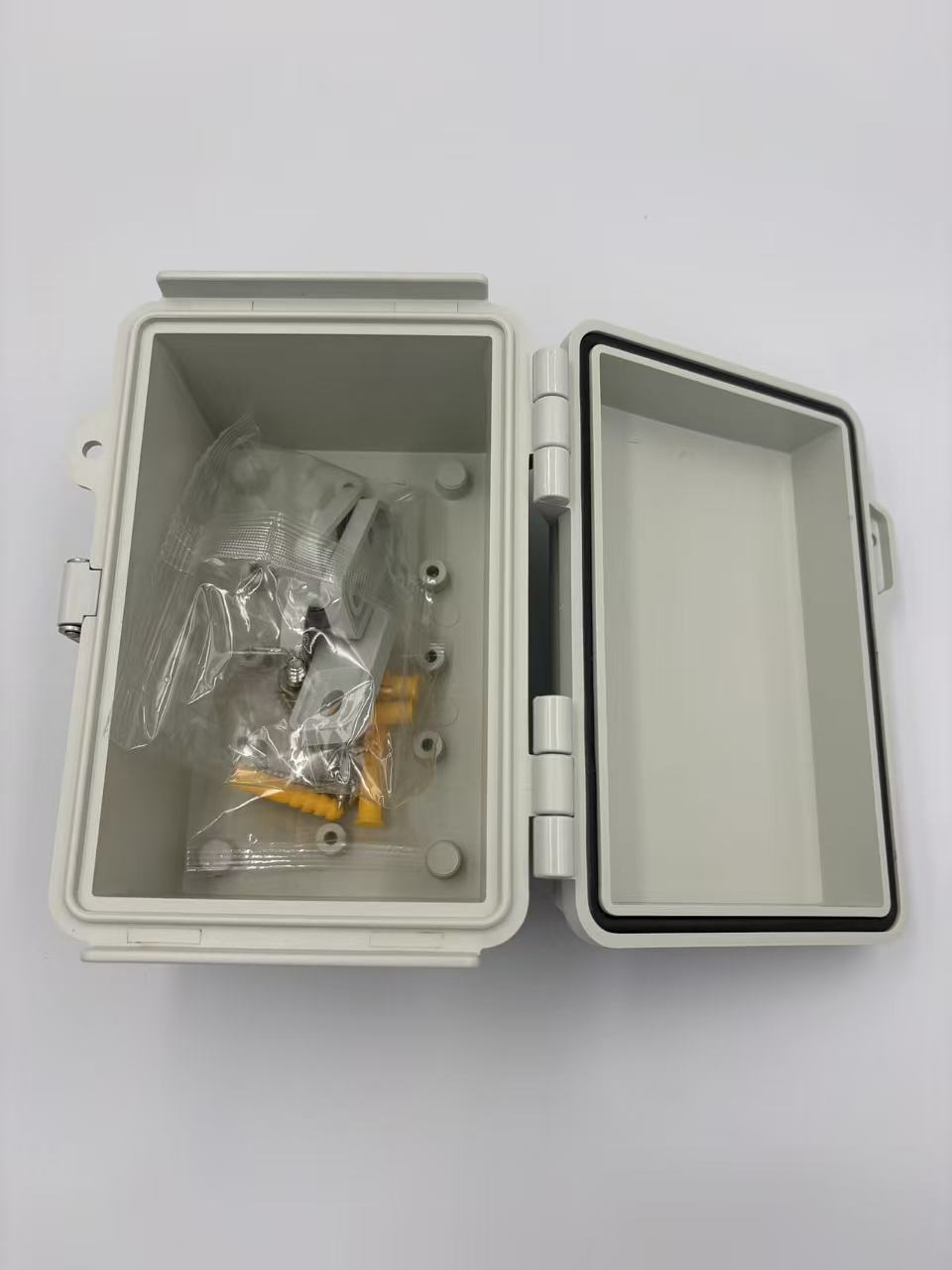
From Prototype to Production
For enclosure projects that will eventually move into volume production, the route may look like this:
3D CAD review
↓
Prototype printing
↓
Support removal / local finishing
↓
Hardware and PCB assembly
↓
Fit check
↓
Customer validation
↓
Design revision if required
↓
Design freeze
↓
Tooling
↓
Trial production
↓
الإنتاج الضخم
The transition from prototype to tooling is an important point.
A dimension that is still uncertain during prototyping should ideally be resolved before the mold is made.
Changing CAD and printing another prototype is relatively straightforward. Changing tooling after production trials have started can involve much more work.

What to Send Us for a 3D-Printed Enclosure Prototype
For a more accurate review and quotation, the following information is useful:
- STEP / STP / 3D CAD file
- required quantity
- preferred material, if already specified
- preferred printing process, if required
- mating parts or assembly information
- PCB dimensions
- connector models or datasheets
- critical dimensions
- threaded insert requirements
- areas requiring special surface finishing
- areas that should not be sanded or bead blasted
- expected final production process
- whether the prototype is for appearance, fit testing or functional validation
For projects that will later move to injection moulding, it is also helpful to tell us that at the beginning.
The prototype can then be reviewed with the next manufacturing stage in mind.
A good enclosure prototype does more than confirm the outside dimensions. It gives the customer a chance to install real components, discover interference, adjust fits and correct details while the design is still flexible.
That is where 3D printing provides the most value before mass production.
Author: Cameron Pritchett
اتصل بنا: mia@hofengfab.com | www.hofengfab.com