




A sheet metal component can look perfect on a drawing, pass dimensional inspection, and still create problems when it reaches final assembly. Holes may be slightly out of position, tabs may need to be forced into slots, or several individually acceptable bends may combine to create a noticeable gap. In many cases, the real problem is not a single manufacturing error. It is the way design, material, forming, welding, finishing, and assembly interact throughout production.
For equipment housings, machine enclosures, control cabinets, brackets, and other fabricated assemblies, good results depend on thinking beyond individual part dimensions. The entire manufacturing sequence needs to be considered before the first sheet is cut.
Good Assembly Starts Before Cutting
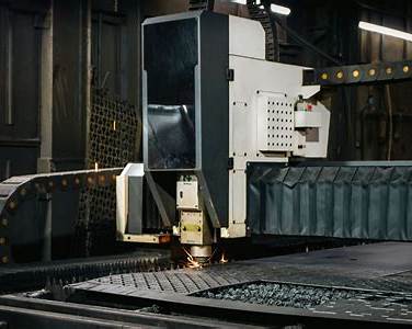
One of the most important stages in sheet metal production happens before material reaches the laser cutter or punching machine.
Engineers first convert the three-dimensional part into an accurate flat pattern. Bend allowances, inside radii, material thickness, grain direction, and forming characteristics all influence the final developed length.
A small error in the flat pattern may appear insignificant while the part is still flat. After several bends, however, that error can shift a flange, mounting hole, or mating surface enough to affect assembly.
This is why design-for-manufacturing reviews are valuable. An experienced precision sheet metal fabricator can evaluate whether bend locations, flange lengths, hole positions, clearances, and assembly features are realistic before production begins.
The objective is not simply to make a drawing manufacturable. It is to make the finished assembly repeatable.
Tolerance Stacking Is Often the Hidden Problem
Every manufacturing process has an allowable amount of variation.
A laser-cut profile may be within tolerance. A bend angle may also be within tolerance. A welded frame may individually meet its drawing requirements. But when several tolerances accumulate in the same direction, the complete assembly can still become difficult to fit.
Consider an enclosure built from several formed panels. If each panel contains multiple bends, a very small dimensional difference at each bend can eventually affect the position of the last mounting surface.
This is called tolerance stacking.
Designers can reduce its effect by establishing clear datums and avoiding unnecessary chains of dimensions. Critical assembly features should reference stable surfaces whenever possible instead of depending on several intermediate bends.
The goal should be predictable relationships between parts rather than extremely tight tolerances everywhere.
Let Parts Locate Themselves
Assembly becomes much easier when parts naturally guide themselves into the correct position.
Tabs and slots are one of the simplest examples. Properly designed tabs can help panels locate before welding or fastening begins. Formed flanges can also create natural reference surfaces.
Slotted mounting holes are useful when limited adjustment is acceptable. Instead of requiring two perfectly aligned round holes, a slot provides room for small manufacturing variations while still allowing the fastener to secure the assembly correctly.
However, clearance must be controlled carefully.
A slot that is too tight defeats the purpose of providing adjustment. A tab that fits too tightly may require force and damage the coating. On the other hand, excessive clearance can allow parts to move during welding and create inconsistent assemblies.
A good sheet metal design does not assume every part will be mathematically perfect. It provides controlled forgiveness where small variations are expected.
Material Thickness Is Not the Only Source of Strength
When a panel feels too flexible, increasing sheet thickness may seem like the easiest solution.
Sometimes it is necessary, but it is not always the most efficient answer.
Bends, flanges, ribs, hems, embossments, and gussets can dramatically improve stiffness without adding the weight and cost associated with thicker material. A properly formed thin panel may perform better than a heavier flat panel.
Thickness also affects manufacturing.
Increasing gauge can require:
- Higher cutting power
- Greater press brake tonnage
- Larger bend radii
- More welding time
- Heavier material handling
- Additional finishing time
Material choice matters as well. Aluminum, mild steel, and stainless steel behave differently during forming and welding. A thickness that works well for one material may create cracking, distortion, or unnecessary processing difficulty in another.
For this reason, material and geometry should be evaluated together rather than separately.
Bend Design Has a Direct Impact on Assembly
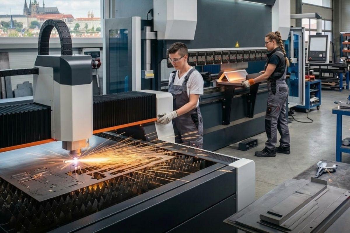
Bending transforms a flat blank into a structural component, but it is also one of the stages where small design decisions can create major downstream problems.
Holes positioned too close to bend lines can distort during forming. Very short flanges may be difficult or impossible to hold correctly against press brake tooling. Deep channels and closed shapes can create tool interference during later bends.
Bend sequence is equally important.
A part may be technically possible to bend, yet require an inefficient sequence or specialized tooling because an earlier flange blocks access to a later bend.
Standardizing bend directions where practical can make production more predictable and reduce setup complexity. Designers should also consider whether the part can physically be removed from the tooling after each operation.
This is another reason early communication between engineering and fabrication teams is valuable. A precision sheet metal fabricator can often identify forming conflicts before tooling is set up, avoiding redesign and rework later.
Welding Can Change a Perfectly Formed Part
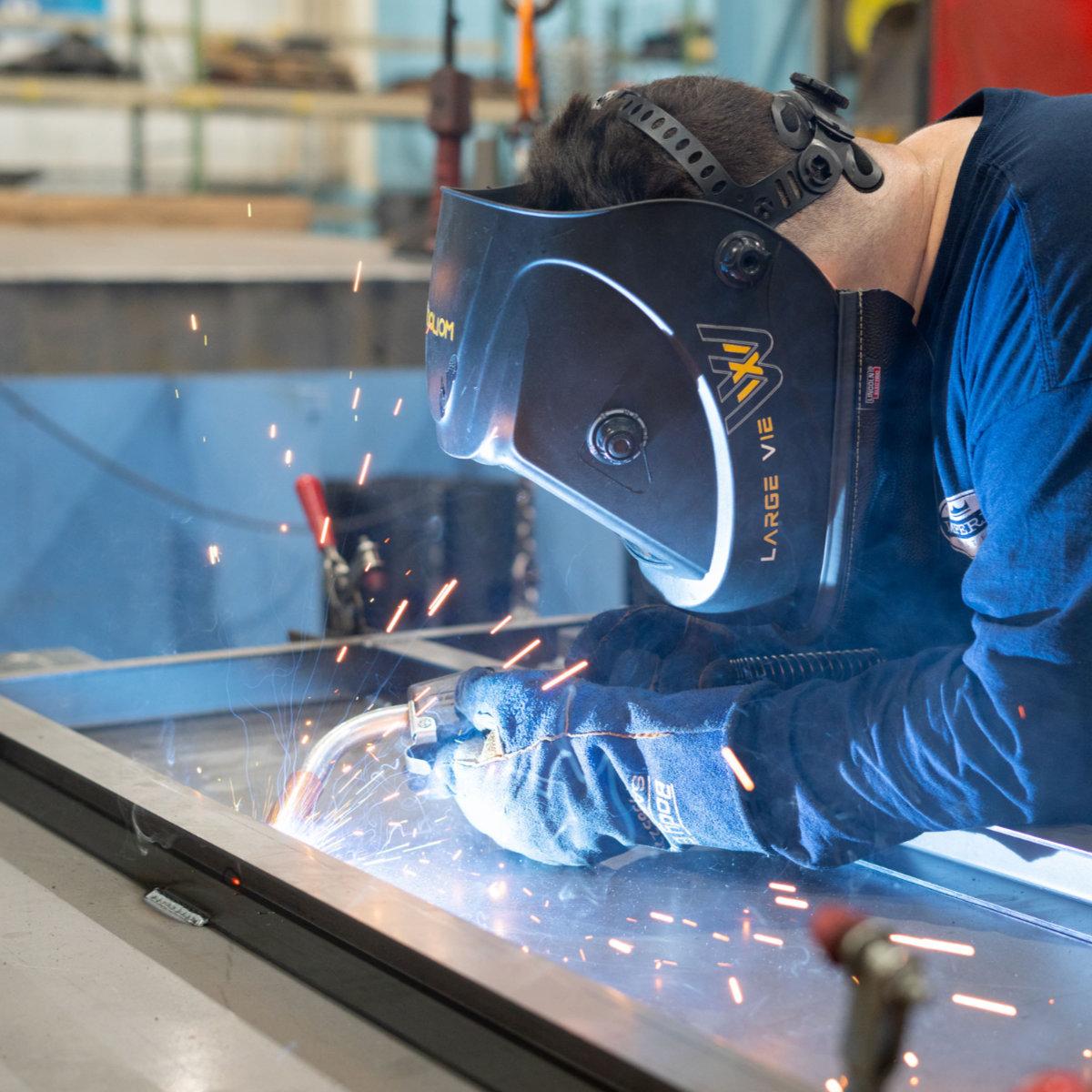
Even when every cut and bend is correct, welding introduces another variable: heat.
Localized heating and cooling can pull panels out of square, distort thin material, or change the relationship between mounting surfaces. Long continuous welds are especially capable of introducing distortion if the sequence is poorly controlled.
Fixtures, tack-welding patterns, balanced welding sequences, and appropriate weld lengths can help control movement.
The assembly method should therefore be considered during design.
Mechanical fasteners provide more opportunity for adjustment and can simplify service or disassembly. Welding offers a permanent connection and clean appearance but provides much less flexibility once the components are fixed in position.
Some products benefit from combining the two methods. Self-locating features can position components first, mechanical fasteners can hold alignment, and selected welds can then provide the required structural strength.
The best method depends on strength, appearance, production volume, maintenance requirements, and cost.
Do Not Forget the Thickness of the Finish
A part that fits correctly before finishing may behave differently after powder coating, painting, plating, or anodizing.
Coatings add material to surfaces.
That additional thickness can reduce hole diameter, tighten slots, interfere with tabs, and change contact between mating surfaces. The effect may be small, but in an assembly with very limited clearance it can be enough to turn a smooth fit into a forced fit.
Finishing requirements should therefore be defined during design rather than added at the end of production.
Areas that need electrical contact, grounding, welding, or very precise mechanical mating may require masking. Drainage and hanging points may also be necessary so pretreatment chemicals and coating materials do not become trapped inside enclosed features.
A well-designed part considers its finished condition, not just the dimensions of the raw metal.
Design for the Entire Manufacturing Process
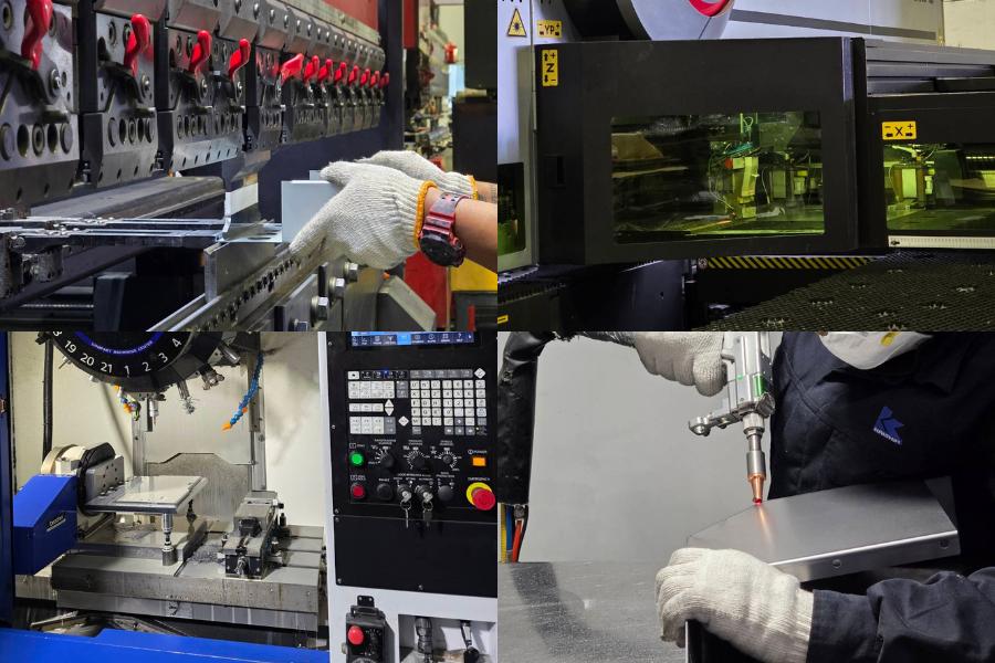
Reliable sheet metal production is rarely the result of one exceptionally accurate machine.
It comes from controlling the relationship between every process:
Design → Flat Pattern → Cutting → Forming → Welding → Finishing → Assembly → Inspection
Changing one step can influence several others.
A thicker sheet changes bending requirements. A tighter slot affects coating clearance. A new weld location can increase distortion. Moving a hole may solve an assembly issue but place it too close to a bend.
For this reason, evaluating the complete manufacturing path usually produces better results than optimizing each operation independently.
The Best Parts Are Easy to Assemble
A useful test of good sheet metal design is simple: can trained operators assemble the product repeatedly without forcing parts, enlarging holes, improvising fixtures, or making manual adjustments?
When components naturally locate themselves, tolerances are distributed intelligently, bends are manufacturable, weld distortion is controlled, and finishing thickness is considered, assembly becomes faster and more consistent.
That consistency reduces more than labor time. It also lowers rework, scrap, inspection problems, and unexpected production delays.
Precision is important, but precision alone cannot compensate for a design that ignores real manufacturing variation. Bringing an experienced precision sheet metal fabricator into the project early helps connect design intent with cutting, bending, welding, finishing, and final assembly—so the parts do not simply meet the drawing, but actually fit together when production begins.
Contact us : mia@hofengfab.com