



When we evaluate a precision-machined component, we do not start by asking whether our equipment can make it. In most cases, modern 5-axis CNC technology can handle surprisingly complex geometries.
The more important question is:
What is the most technically sound and commercially efficient way to turn the raw Chromium-molybdenum alloy steel material into the final part?
For this type of component, I would separate blanking from mecanizado de precisión rather than automatically trying to do everything on a 5-axis machining center.
calls for steel at 18–22 HRC, with a relatively compact C-shaped geometry, circular internal and external profiles, angled surfaces, mounting ears, drilled/tapped features, pockets and multiple small radii. It also specifies a final Black Oxide finish.
That combination makes the manufacturing route particularly important.
- Start With the Material, Not the Machine
Specifies at approximately 18–22 HRC. That is an important manufacturing detail.
Chromium-molybdenum alloy steel is machining behavior changes significantly with its heat-treatment condition. Material around 18–22 HRC is considerably easier to machine than hardened Chromium-molybdenum alloy steel, although the softer condition can have a tendency to produce less clean cutting behavior than some pre-hardened conditions.
This is why I would not simply tell the shop:
“Use Chromium-molybdenum alloy steel and machine it.”
The material certificate should confirm at least:
- Material grade
- Heat-treatment condition
- Hardness
- Material specification
- Plate/bar thickness
- Mill certificate
For production work, Chromium-molybdenum alloy steel is not a sufficient material description by itself. Two pieces of Chromium-molybdenum alloy steel can behave very differently during machining if their hardness and supply condition are different.
2. The Real Manufacturing Decision: How Should We Blank the Part?
For this component, there are three realistic approaches:
- Saw-cut blank + 5-axis CNC
- Waterjet blank + 5-axis CNC
- 5-axis CNC directly from solid stock
All three are technically possible.
They are not equally economical.
3. My Preferred Method for a Cost-Sensitive Production Part
If the customer does not specifically require waterjet, my first choice would normally be:
stock → band-saw blank → 5-axis Mecanizado CNC
The saw does not need to reproduce the final C-shaped profile.
It only needs to produce a manageable rectangular or near-rectangular blank with sufficient machining allowance.
For example, based on the approximately 4-inch finished envelope shown in the drawing, the blank might be around:
200 × 200 mm
with the thickness selected according to the required finished section and available stock.
The exact blank size should be finalized from the customer's CAD model and the actual material thickness.
Why?
Because the saw is doing what it is good at:
removing large amounts of inexpensive material quickly.
The CNC is then doing what it is good at:
producing controlled geometry, tolerances, holes, pockets, radii and surface finishes.
This division of labor is often more important to the final price than whether the shop owns a 3-axis or 5-axis machine.
4. When Waterjet Makes More Sense
If the customer specifically requests:
Waterjet + CNCthen I would not try to replace the waterjet simply because we have a 5-axis machining center.
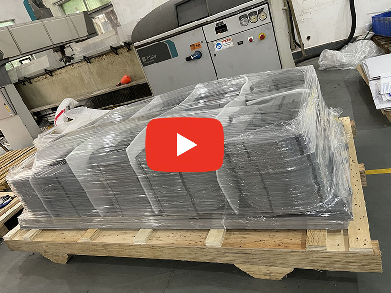
For this particular part, waterjet can produce a near-net-shape blank following the major C-shaped profile.
The process becomes:
Plate → Waterjet blanking → 5-axis CNC finishing → inspection → Black Oxide
This has a major advantage:
The waterjet can cut the basic outside profile and opening, while CNC machining establishes the actual finished dimensions.
However, I would not make the waterjet cut exactly to the final drawing dimensions.
The waterjet profile should intentionally leave machining allowance.
5. How Much Waterjet Allowance Should We Leave?
This is one area where I would avoid using a universal number.
The allowance depends on:
- Waterjet accuracy
- Plate thickness
- Cutting quality
- Material condition
- Final CNC tolerance
- Whether the profile will be completely recut
- Fixturing requirements
- Production quantity
For a typical precision machining workflow, I would discuss an allowance in the neighborhood of 0.5–1.0 mm per machining side as a starting point, then confirm it against the waterjet supplier's actual capability and the drawing tolerances.
The important principle is:
Waterjet = near-net shape. CNC = final geometry.
Do not expect the waterjet to establish a critical CNC-machined diameter or profile simply because the numerical dimension appears achievable.
6. Why I Would Not Use 5-Axis CNC as the “Cutting Method” by Default
This is probably the most important manufacturing point for this part.
A 5-axis machining center can absolutely cut the entire component from a solid plate.
But capability is not the same as process efficiency.
If we start with a 200 × 200 mm block and ask the CNC to remove everything that does not belong to the part, the machine will spend considerable time converting solid steel into chips.
That creates:
- Higher machine time
- Higher tooling consumption
- Higher material waste
- Higher spindle load
- More roughing operations
- More opportunities for vibration
- Higher cost per part
The fact that the machine is 5-axis does not eliminate these issues.
A 5-axis machine gives us access and orientation capability. It does not make bulk material removal free.
That distinction is often overlooked when quoting custom CNC components.
7. The Better Way to Use a 5-Axis Machine
For this part, I would use the 5-axis machine primarily for the geometry that actually benefits from it.
The drawing contains:
- Circular internal and external profiles
- Angled surfaces
- Small radii
- Upper and lower mounting ears
- Bolt/hinge pocket areas
- Chamfers
- Multiple drilled features
- M10 × 1.5 thread
- A relatively thin C-shaped finished section
This is exactly where 5-axis machining becomes useful.
Instead of using five-axis capability simply as an expensive replacement for a saw, use it to reduce setups and improve geometric consistency.
8. Fixturing Is More Important Than Most People Think
There is another practical issue with this component.
Once the internal material has been removed, the part becomes a relatively open C-shaped component.
That means the part becomes progressively more difficult to clamp.
This leads to a common mistake:
Cut the entire part free first, then try to fixture it for finishing.
I would do the opposite.
Keep material for workholding as long as possible.
The rough blank can initially retain a small machining/fixturing area.
The CNC can machine the critical internal and external features while the workpiece is still rigid.
Only near the end of the process should the remaining sacrificial material or tabs be removed.
This gives us:
- Better rigidity
- Less vibration
- Better dimensional stability
- More reliable finishing
- Easier tool access
For a small 4140 component like this, workholding strategy can have a larger effect on part quality than simply increasing machine capability.
9. A Practical CNC Process Route
If I were preparing the manufacturing route for this drawing, I would consider something close to the following.
Option A — Saw + 5-Axis CNC
Operation 10 — Raw Material
Chromium-molybdenum alloy steel, 18–22 HRC.
Verify material certificate and hardness.
Operation 20 — Band Saw
Cut rectangular blank with sufficient stock for CNC machining.
Operation 30 — First CNC Setup
Establish datum surfaces.
Rough-machine:
- Outside profile
- Inside opening
- Major circular surfaces
- Mounting ears
Leave controlled finishing stock.
Operation 40 — 5-Axis Reorientation
Machine:
- Angled faces
- Secondary profiles
- Pockets
- R0.100/R0.219/R0.250 features
- Chamfers
Operation 50 — Drilling/Tapping
Machine the specified holes and:
M10 × 1.5 thread
Operation 60 — Final Profile Finishing
Finish the critical internal and external geometry.
Operation 70 — Deburring
Remove burrs from:
- Waterjet/saw interface
- Milled edges
- Holes
- Threads
- Chamfers
Operation 80 — Inspection
Verify critical dimensions and geometric relationships.
Operation 90 — Black Oxide
Apply the specified black oxide finish.
10. If the Customer Requires Waterjet
Then I would change only the front end of the process:
Recommended route
Plate → Waterjet near-net blank → 5-axis CNC → drilling/tapping → deburring → inspection → Black Oxide
The key is that the waterjet should not attempt to replace CNC finishing.
The waterjet's job is to reduce the amount of material that the CNC has to remove.
The CNC's job is to establish the final engineering geometry.
This distinction makes the process much easier to control.
11. What About Corte por láser?
For this particular component, laser would not be my first choice unless the material thickness, machine capability and customer's requirements have already been validated.
The reason is not that laser cannot cut Chromium-molybdenum alloy steel.
It can.
The issue is that we are ultimately producing a precision-machined mechanical component, and I would rather avoid introducing unnecessary thermal effects into areas that will subsequently become critical machined surfaces.
If waterjet is already specified, it is a much cleaner match for a near-net blanking operation.
12. Waterjet vs. Saw: My Engineering Decision
I would make the decision based on production requirements rather than simply choosing the more sophisticated process.
| Requirement | Recommended blanking |
|---|---|
| Prototype, low quantity | Band saw + CNC |
| Small production quantity | Band saw + CNC |
| High material-removal volume | Waterjet + CNC |
| Customer specifically specifies waterjet | Waterjet + CNC |
| Complex 2D profile before CNC | Waterjet |
| Lowest material cost | Saw, depending on stock geometry |
| Need to minimize CNC roughing | Waterjet |
| Need angled pre-cut geometry | 5-axis waterjet |
| Final precision geometry | 5-axis CNC |
This is why I would not automatically quote “5-axis CNC cutting” as the blanking process.
5-axis CNC is a machining strategy, not necessarily the best blanking strategy.
13. One More Point: Do Not Quote From the 2D Drawing Alone
It gives us enough information to understand the manufacturing concept, but before releasing production, I would want the customer's 3D CAD model or STEP file.
This particular component contains several features whose manufacturability is much easier to verify in 3D:
- Section H-H
- Angled surfaces
- Internal Ø2.650 profile
- Ø4.000 outer geometry
- Upper/lower ear geometry
- Hinge/bolt pockets
- R0.100 and R0.250 transitions
- Relative position of the holes
A 2D drawing tells us what the part must be.
The 3D model helps us determine how efficiently we can make it.
That difference matters when choosing between waterjet, saw cutting and five-axis machining.
14. My Recommended Manufacturing Philosophy
For this type of part, I would use the following principle:
Do not ask the most expensive machine to perform the cheapest operation.
Use the saw to remove simple bulk material.
Use waterjet when a complex near-net profile saves significant CNC time.
Use 5-axis CNC where five-axis access actually creates value.
And use the final CNC operations to establish the dimensions that matter.
For the specific clamp in this drawing, my preferred routes would therefore be:
If waterjet is required by the customer:
18–22 HRC → Waterjet near-net blank → 5-axis CNC finish machining → inspection → Black Oxide
If the customer only cares about the final part:
18–22 HRC → Band-saw blank → 5-axis CNC machining → inspection → Black Oxide
That is the approach I would use when preparing a production quotation because it balances machinability, fixturing, material utilization, cycle time and dimensional control, rather than choosing a process simply because the machine has more axes.